
Course Introduction
Wireless Digital Communications
The objective of a digital communications system is to share information (in the form of a digital signal) between multiple points.
A traditional digital communication system can be represented with a signal flow diagram, which is a series of "blocks" that are connected together, each of which perform various data and signal processing operations. Some excerpts of a communication system from a course lab in LabVIEW are given:
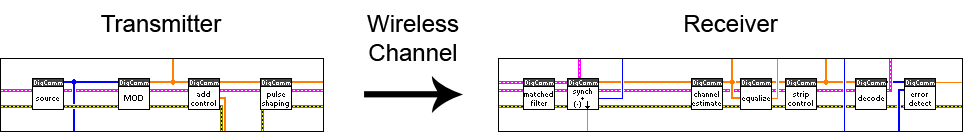
The system consists of a:
- Transmitter - transforms information (bits) to a continuous signal that may be sent over the wireless channel
- Receiver - senses and locks on to the transmitted signal, then transforming it back to bits.
The system is complicated by the Wireless Channel, which distorts the transmitted continuous signal.
The information (bits) are generated by the first block ("source"), while the last block ("error detect") compares the received bits to the original in order to determine the error rate.
There are fundamental processes that occur in a digital wireless communication system, that are illustrated by the blocks of the diagram, and will be taught in the course:
- Modulation / Decoding - "MOD" / "decode" blocks - Transforming the information (bits) to signal changes, and vice-versa.
- Filtering - "pulse shaping", "matched filter" blocks - Filtering operations that bandlimit the signal and reduce the effects of the Wireless Channel.
- Synchronization - "add control", "synch" blocks - Allow the Receiver to lock to the transmitted signal
- Equalization - "channel estimate", "equalize" blocks - Corrects the signal for changes that occur over the Wireless Channel
There are also additional necessary steps that are covered, but are performed by the USRP:
- Up/down Conversion - Raising/lowering the baseband signal to/from the proper frequency.
Some of these blocks will be re-constructed by the student in the course lab.
For further introductory material, see NI's Understanding the Fundamentals of Digital Communications.
Designing with LabVIEW and the USRP software-defined radio
LabVIEW and the USRP are key to the hands-on learning method used in the course.
- LabVIEW is an intuitive graphical development environment that is used to visually program the systems and processes used in the course.
- The USRP is a hardware peripheral that enables nearly all of the digital communication processes - listed in the previous section - to be programmed in software. (Traditionally, dedicated hardware and silicon were required).
In LabVIEW, functions are called VIs, or Virtual Instruments, since they mimic real-life instruments. They have inputs, outputs, and perform some function, much like a function in any programming language.
Each of the blocks shown inside of the Transmitter and Receiver in the course lab diagram are VIs that are used to construct the example communications system.

VIs are connected together using wires. The style and color of the wire represent the data type of what is connected to the wire.
For example. the "MOD" VI has a thick blue wire as an input, representing an integer array (the bits to be modulated), as well as a thick orange wire as an output, representing an array of symbols (complex numbers representing waveform changes, ie. phase).
VIs are constructed using existing (typically, simpler) VIs, many which can perform the same operations that are seen in traditional programming, such as mathematical operations (e.g. add, multiply), conditional operations (e.g. if, else) and loops (e.g. while, for).
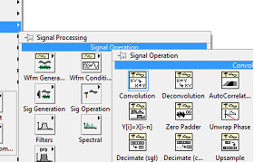
There are a large number of interface, communications and signal processing VIs that are readily available for use. These make interfacing with the USRP (which accepts samples of the baseband signal), as well as many of the needed modulation and filtering operations, as simple as inserting a VI and connecting appropriate the wires.
(For more information about LabVIEW and the USRP, please visit the Equipment page)