[ RS-232 | RS-485 | RJ-45 | PS/2 | Null Modem | USB | Firewire ]
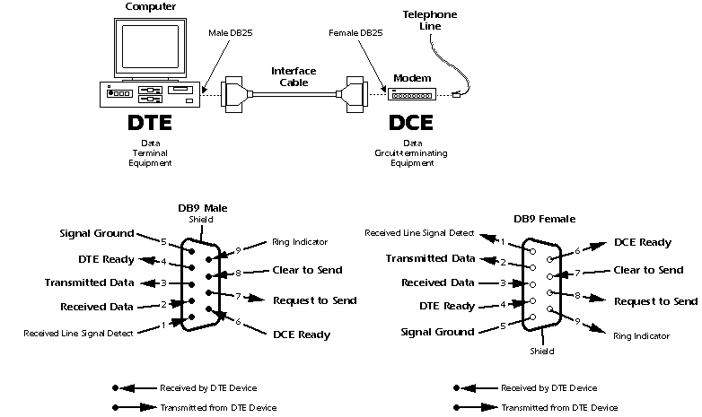
RS 232 is well-known due to popularity of today's PC's. However, as it is designed in 1950's, DTE and DCE became mind-boggling names now. As far as I know, the serial port of my laptop is a male socket and so, it must be a DTE.

So, it's straight forward that those two sockets (mail and female) could be connected by a straight cable ( in which pin1 to pin 1, pin2 to pin2 ... and pin 9 to pin 9). In that way, one end's RTS and the other's CTS is in the same wire. TD and RD are also in such a case.
RS-485 & RS-422
So, what is the main difference between RS 232 and RS 422 & 485? The RS 232 signals are represented by voltage levels with respect to ground. There is a wire for each signal, together with the ground signal (reference for voltage levels). This interface is useful for point-to-point communication at slow speeds. For example, port COM1 in a PC can be used for a mouse, port COM2 for a modem, etc. This is an example of point-to-point communication: one port, one device. Due to the way the signals are connected, a common ground is required. This implies limited cable length - about 30 to 60 meters maximum. (Main problems are interference and resistance of the cable.) Shortly, RS 232 was designed for communication of local devices, and supports one transmitter and one receiver.
RS 422 & 485 uses a different principle: Each signal uses one twistedpair (TP) line - two wires twisted around themselves. We're talking 'Balanced data transmission', or 'Differential voltage transmission'. Simply, let's label one of the TP wires 'A' and the other one 'B'. Then, the signal is inactive when the voltage at A is negative and the voltage at B is positive. Otherwise, the signal is active, A is positive and B is negative. Of course, the difference between the wires A and B matters. For RS 422 & 485 the cable can be up to 1200 meters (4000 feet) long, and commonly available circuits work at 2.5 MB/s transfer rate.
What is the difference between RS 422 and RS 485? Electrical principle is the same: both use differential transmitters with alternating voltages 0 and 5V. However, RS 422 is intended for point-to-point communications, like RS 232. RS 422 uses two separate TP wires, data can be transferred in both directions simultaneously. RS 422 is often used to extend a RS 232 line, or in industrial environments.
RS 485 is used for multipoint communications: more devices may be connected to a single signal cable - similar to e.g. ETHERNET networks, which use coaxial cable. Most RS 485 systems use Master/Slave architecture, where each slave unit has its unique address and responds only to packets addressed to this unit. These packets are generated by Master (e.g. PC), which periodically polls all connected slave units.
RJ-45 ( Ethernet 802.3)
RJ-45 connector is widely used to connect computers in a Ethernet, and to hub (layer1 device), bridges and switches (layer 2device) and routers (layer 3)... In 10base-T, pin 1and 2 are used for TX and 3-6 are for Rx. Differential signals are used. That's why we need a pair of wires for one direction.
Use only four of the eight pins. Pins 1 and 2 must be a pair, and pins 3 and 6 must be a pair.
	                  Function     Pin#               Pin#
	                 -------------------------------------
	                    TX+        1    <-------->   1
	                    TX-        2    <-------->   2
	                    RX+        3    <-------->   3
	                    RX-        6    <-------->   6
	                 -------------------------------------
	                         STRAIGHT THOUGH CABLE
To allow for a straight-through cable, the hub provides an internal transmit/receive crossover function. This means the transmit circuit of the network adapter is connected to the receive circuit of the hub and vice versa.
Pinout for the RJ45 Connector
	   PINOUT FOR RJ45 CABLE CONNECTOR:
	   --------------------------------
	               ----------              --------------------------
	            1 |--        |          8 |------------              |
	            2 |--        |          7 |------------              |
	            3 |--         ---       6 |------------              |
	            4 |--            |      5 |------------              |
	            5 |--            |      4 |------------              |
	            6 |--         ---       3 |------------              |
	            7 |--        |          2 |------------              |
	            8 |--        |          1 |------------              |
	               ----------              --------------------------
	                  END                             TOP
Pin Name And Function
A detailed graph for coloring scheme (EIA-568) is:
Why the Gigabit Ethernet need all 8 pins? It is because it use 4 pairs (each transmits 250Mbps duplex) of wires. So, it is somewhat like parallel transmissions. The 250Mbps speed is realized by use 5-level signaling which has a 6db less than 3-level signaling used in 100M Ethernet. However, this will be compensated by an FEC scheme which resides upon this PHY layer. Seems, only very short distance (25-100m) can be supported in this kind of wiring and a common ground has to be assumed.
Why it is null-modem? Because, when PC connects to a modem, PC is a DTE, and modem is DCE. When Modem is null, we have to connect 2 DTEs. The purpose of a null-modem cable is to permit two RS-232 "DTE" devices to communicate with each other without modems or other communication devices (i.e., "DCE"s) between them. It is as same as a cross-over cable linking 2 serial ports of computers. 2 female sockets in both ends of the line.
To achieve this, the most obvious connection is that the TD signal of one device must be connected to the RD input of the other device (and vice versa).Use this female-to-female cable in any application where you wish to connect two DTE devices (for example, two computers). A male-to-male equivalent of this cable would be used to connect two DCE devices.
For input devices like keyboards and mouse, PS/2 is not compatible with RS-232 ( think a mouse who connected to the serial port of some old workstations ). It has 6 pins which only has 4 functional pins : DATA, Ground, VCC and clock.
The PS/2 mouse and keyboard implement a
bidirectional synchronous serial protocol. The bus is "idle" when both lines
are high (open-collector). This is the only state where the keyboard/mouse is
allowed begin transmitting data. The host has ultimate control over the bus and
may inhibit communication at any time by pulling the Clock line low.
The device always generates the clock signal.
If the host wants to send data, it must first inhibit communication from the
device by pulling Clock low. The host then pulls Data low and releases Clock.
This is the "Request-to-Send" state and signals the device to start generating
clock pulses.
Summary: Bus States
Data = high, Clock = high: Idle state.
Data = high, Clock = low: Communication Inhibited.
Data = low, Clock = high: Host Request-to-Send
All data is transmitted one byte at a time and each byte is sent in a frame consisting of 11-12 bits. These bits are:
The parity bit is set if there is an even number
of 1's in the data bits and reset (0) if there is an odd number of 1's in the
data bits. The number of 1's in the data bits plus the parity bit always add up
to an odd number (odd parity.) This is used for error detection. The
keyboard/mouse must check this bit and if incorrect it should respond as if it
had received an invalid command.
Data sent from the device to the host is read on the falling edge of the clock signal; data sent from the host to the device is read on the rising edge. The clock frequency must be in the range 10 - 16.7 kHz. This means clock must be high for 30 - 50 microseconds and low for 30 - 50 microseconds.. If you're designing a keyboard, mouse, or host emulator, you should modify/sample the Data line in the middle of each cell. I.e. 15 - 25 microseconds after the appropriate clock transition. Again, the keyboard/mouse always generates the clock signal, but the host always has ultimate control over communication. Timing is absolutely crucial.
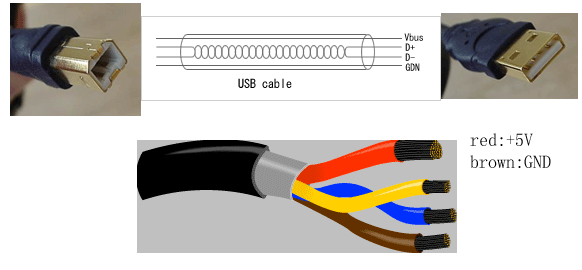
For very short distance, less than 5m, a high-speed serial transmission up to 480Mbps is possible. The USB cable has 2 type, Socket A is connect to computers (hosts) for upstream traffic and B is connect to device (digital cameras, etc) for downstream traffic..

Transmission Process:
When the host powers up, it queries all of the devices connected to the bus and assigns each one an address. This process is called enumeration -- devices are also enumerated when they connect to the bus. The host also finds out from each device what type of data transfer it wishes to perform:
The host can also send commands or query parameters with control packets.
As devices are enumerated, the host is keeping track of the total bandwidth that all of the isochronous and interrupt devices are requesting. They can consume up to 90 percent of the 480 Mbps of bandwidth that is available. After 90 percent is used up, the host denies access to any other isochronous or interrupt devices. Control packets and packets for bulk transfers use any bandwidth left over (at least 10 percent).
The Universal Serial Bus divides the available bandwidth into frames, and the host controls the frames. Frames contain 1,500 bytes, and a new frame starts every millisecond. During a frame, isochronous and interrupt devices get a slot so they are guaranteed the bandwidth they need. Bulk and control transfers use whatever space is left. The technical links at the end of the article contain lots of detail if you would like to learn more.
Firewire
Converters
Reference Link:
* writings are including excerpts from other online tutorials.