Physical Layer: Frame Capture Effect Implementation
If the receiver is already in RX state when a new signal arrives, the decision whether to switch to the new signal is made by a frame-capture policy. In the calibrated simulator, the frame-capture effect is implemented as an enhancement of the default ns-3 version. The frame capture effect is in part a feature of modern wireless devices to switch to a stronger signal during the reception of a weaker frame. Suppose that a node is receiving a relatively weak signal, while a stronger frame is arriving. Due to the additional interference, the SINR of the currently received packet drops and the correct reception will fail. If the receiver cannot stop the current reception and switch to the stronger signal, it will determine that the received data is corrupt only at the frame’s end. The stronger frame is lost as well. More sophisticated receivers can support frame body-capture and tune to the stronger frame. This stronger frame then can be correctly received. Even simple receivers, however, are capable of frame capture if the two frames with significantly different power levels arrive nearly simultaneously. A detailed description of an implementation of the frame-capture effect in ns-3 simulator can be found in [1]. We largely followed this description except for several modifications and simplifications listed below. The frame-capture mechanism is implemented primarily in the InterferenceHelper, WifiStateHelper, and YansWifiPhy classes.
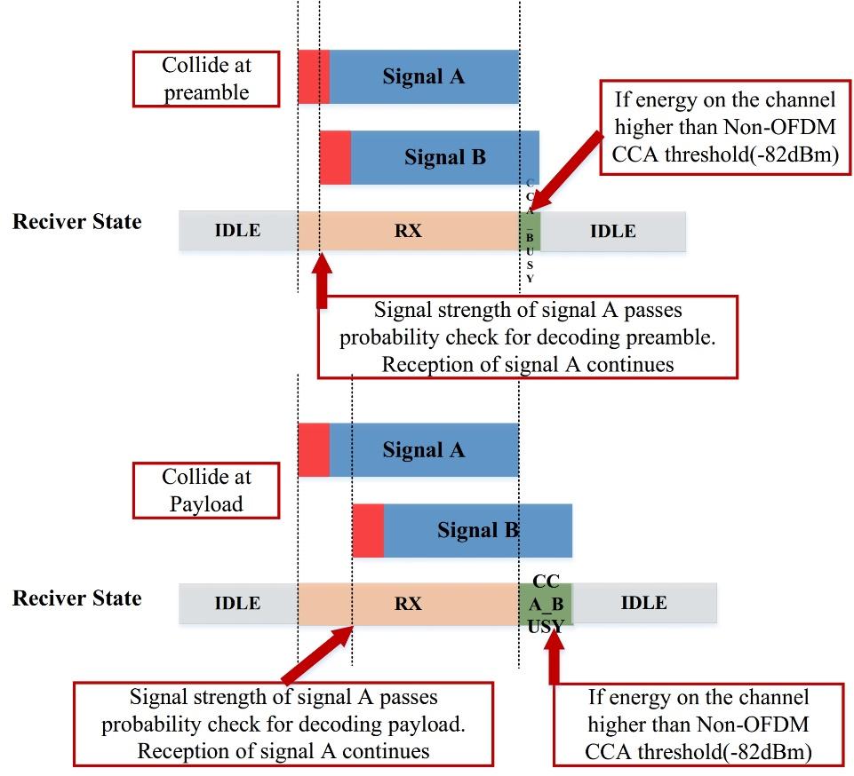
Within the receiving stage are two different capture types. Preamble capture refers to the case where the second transmission arrives while preamble reception of the first transmission is still ongoing. Frame-capture refers to the case where preamble reception of the first transmission is already complete and frame body or payload reception is ongoing when the second transmission arrives at the receiver (this discussion uses the terms frame body and payload interchangeably).
Preamble Capture
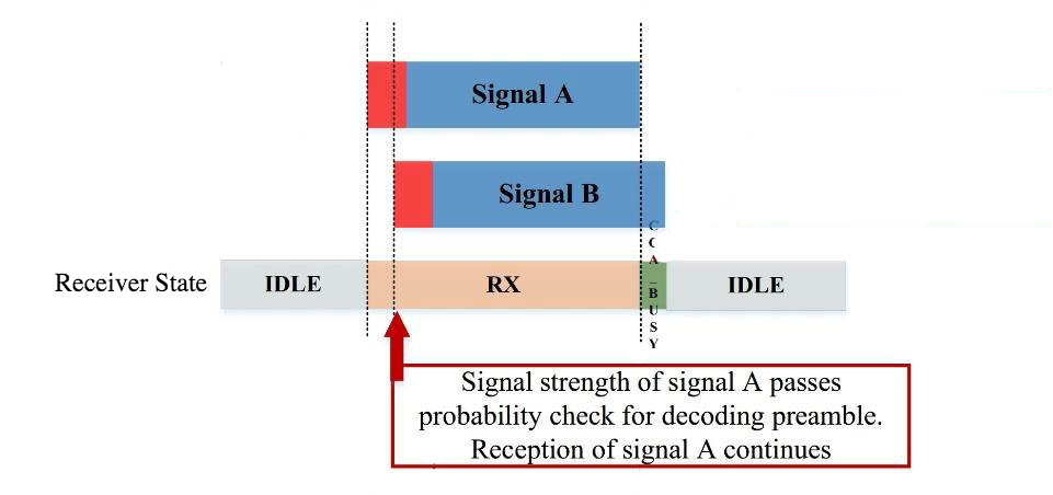
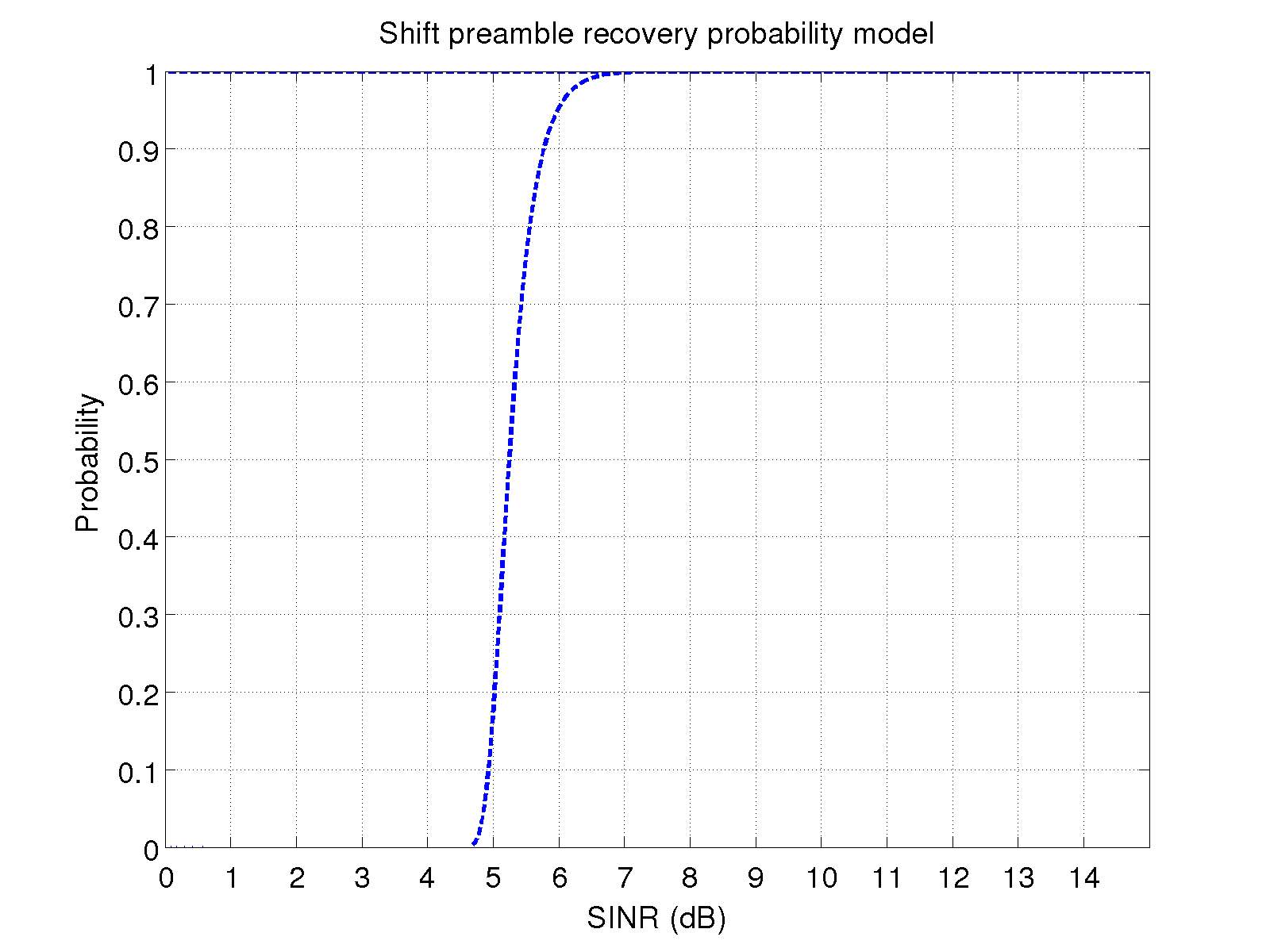
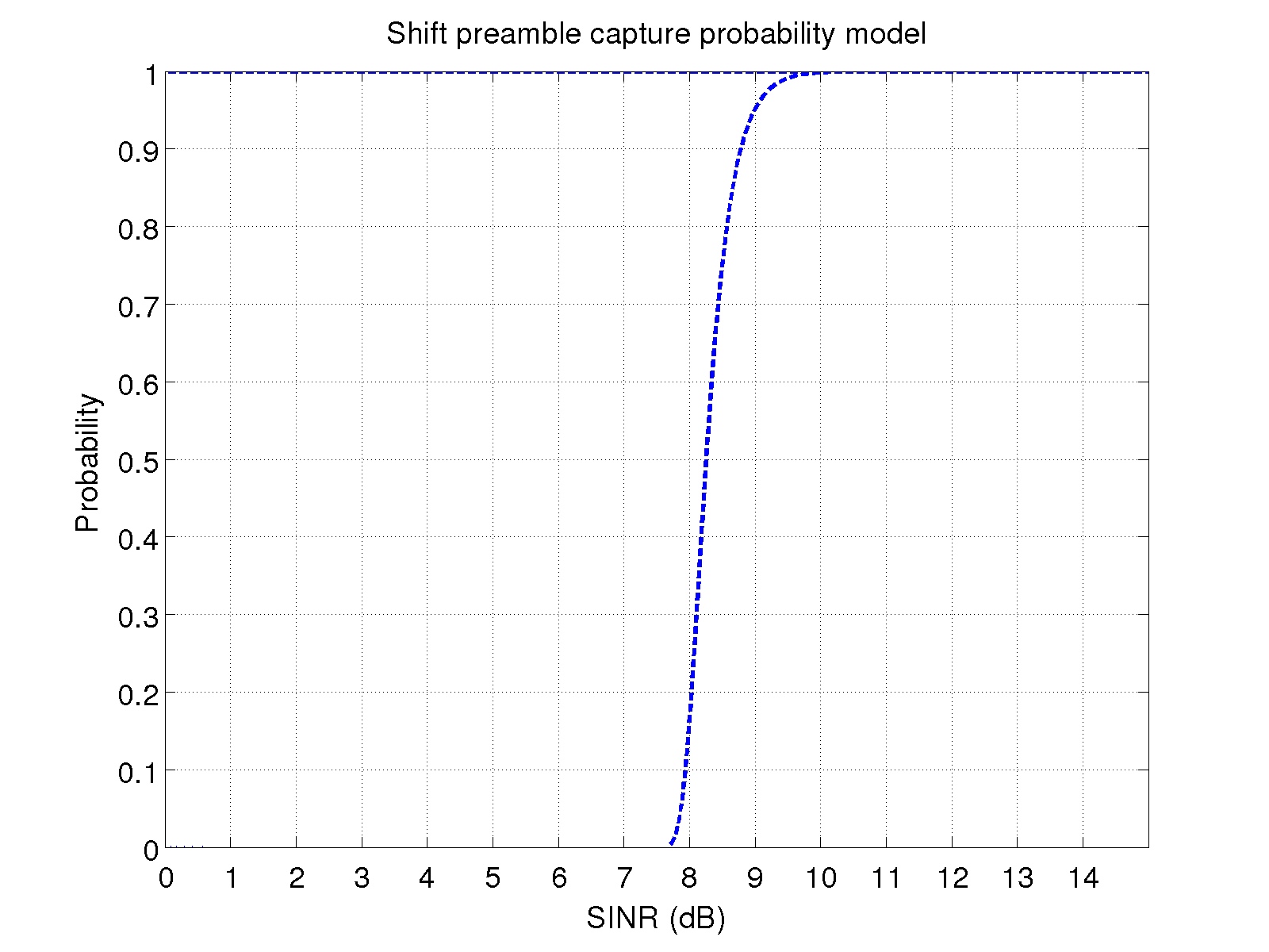
In the preamble capture scenario shown in Figure 1, signal A is being received when signal B arrives. The current SINR of signal A is updated with the interference from signal B for the calculation of the preamble decoding probability. The probability model of successful decoding is plotting in Figure 2. If signal A passes the probability check (i.e., signal A can still be decoded successfully) the reception will continue and signal B is ignored. However, if signal A fails the probability check (i.e., the preamble of signal A cannot be decoded successfully at this time), the reception of signal A will be terminated and signal B will be evaluated. If the SINR for signal B, while considering signal A as interference, is strong enough to pass the probability check for capturing the signal, the receiver will switch to the stronger signal B. If signal B cannot pass the capture-probability check either, the receiver will ignore both signals and switch to CCA_BUSY mode. The probability model we used for calculating the preamble-capture probability is shown in Figure 3. It is also a shifted version of default ns-3 probability model for decoding the OFDM 3 Mbps signal. Since there are no strong references or tests to indicate which probability models for preamble decoding and capture apply to the devices in the field test, this model was also empirically calibrated. That is, models with different dB shifts were tested in the simulation to find the dB shift that creates the simulation results closest to the field test results. The selected models generate comparatively better matching simulation results to field test results.
Payload Capture
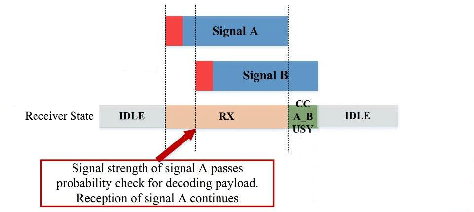
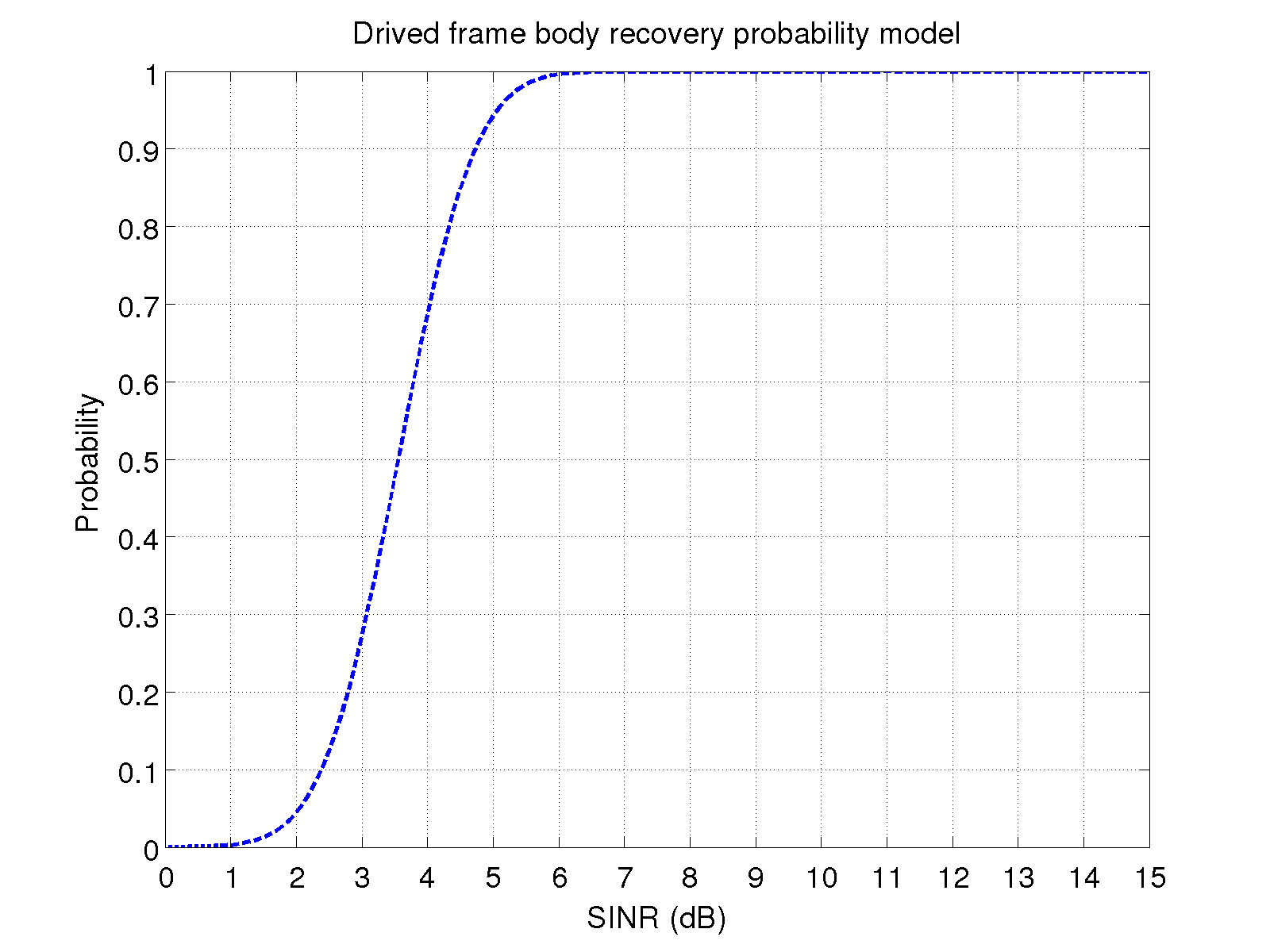
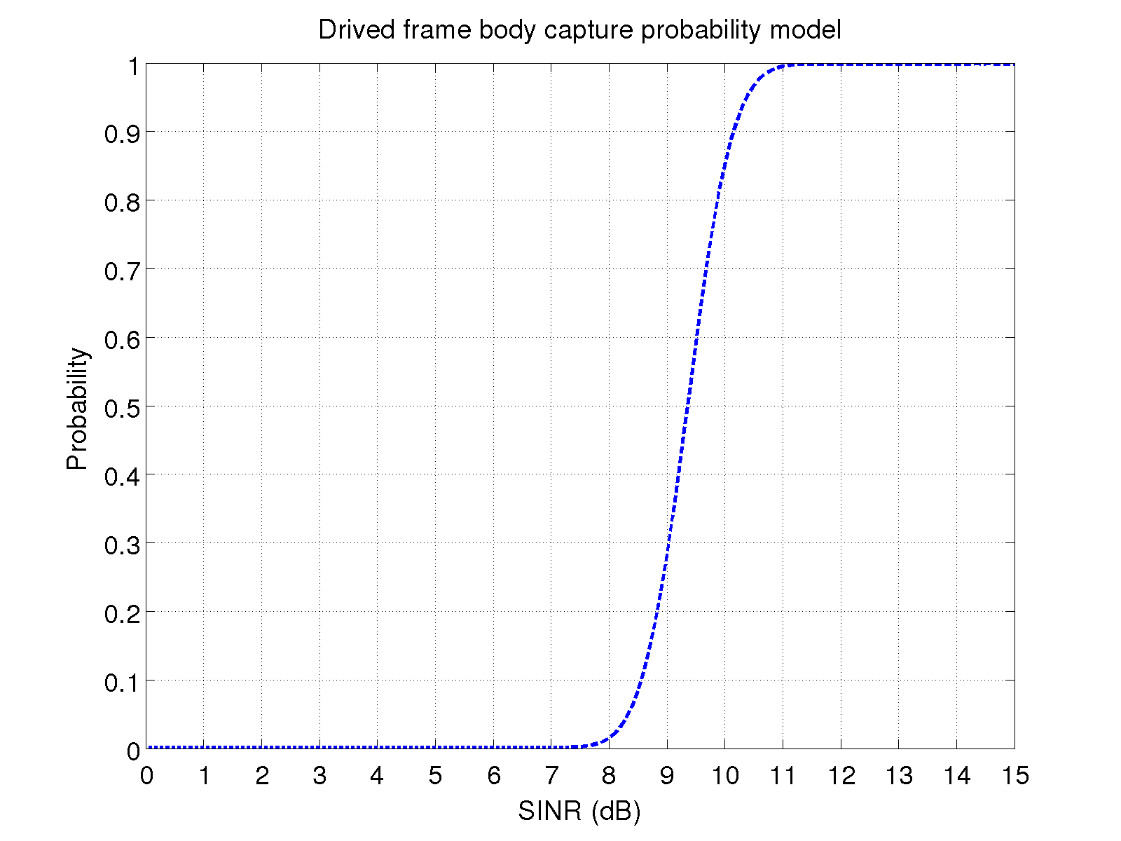
The procedure of payload capture is similar to that of the preamble capture (see Figure 4). In this instance, signal B arrives while the payload of packet A is being received. The simulator calculates the SINR values as described before. The main difference lies in the probability models used for determining successful payload decoding and payload capture based on this SINR value. We fit the probability model to the data obtained from a hardware test for DSRC 6 Mbps channel. The model for payload decoding is derived based on the results for the sender-first case. The sender-first case indicates the scenario in which the receiver node synchronizes to the signal from the sender before other interference signals arrive. From this case, we can determine under what SINR condition the signal from the sender can be still decoded with increased interferences. The probability model for payload capture is obtained from the results of the sender-last case. The sender-last case indicates the scenario in which the receiver node is receiving another signal while the signal from the sender is arriving. From this case, we can determine under what circumstance the receiver can switch to the signal from the sender. The hardware test results showed that the probability of successful packet reception can change at the same SINR when the received power levels are very low. We have not accounted for this variation since the simulation results generally showed a good fit without modeling this additional detail. We chose probability values from measurements at the higher received power levels, specifically the mean probability of the received power levels of -45 dBm and -55 dBm, which appeared to be most stable and representative. This processed data is used for fitting the error model. The error model we use is based on error function,  . The general format of the model is
  . By fitting the data to this model, parameters a, b, c and d can be determined. The values for a, b, c and d in the payload decoding case are 0.4997, 3.557, 1.292 and 0.5 respectively. The corresponding values in the payload capture case are 0.4989, 9.356, 0.8722 and 0.5 respectively. The derived models are plotted in Figure 5 and Figure 6.
State Transitions in Frame Capture
Depending on the timing and A and B’s signal strengths, there are a few different possibilities to receive/drop A or B, or drop both. Let us take a closer look at these situations:
First Sender Success:
Figure 7 illustrates the state transition in the case that the reception of signal A continues and signal B is ignored. Notice that there is no state transition when the collision starts. Notice also that after finishing the reception of signal A, the remainder of B’s transmission may trigger the CCA_BUSY state. The decision of triggering CCA_BUSY state after finishing the reception of signal A is made by comparing the energy on the channel caused by the remainder of B signal with the non-OFDM CCA threshold (i.e., -82 dBm). If the energy exceeds this threshold, the state of the receiver is set to CCA_BUSY.
Last Sender Success:
As shown in Figure 8, if signal A cannot pass the probability check for decoding after the collision, the reception is immediately aborted and the state will switch to IDLE. At the same time, the reception of the new signal B has started and the state switches back to RX. In the default ns-3 version, the reception process of signal A cannot be interrupted. Hence we modified WifiStateHelper by adding a function SwitchFromRxAbort(). The function is called when frame capture is triggered and implements aborting the current RX state and switching to IDLE.
No Success:
Let us now consider the case where neither signal is strong enough: the reception of the first packet cannot continue and the reception of signal B cannot start, both due to low SINRs. This raises the question of how the channel state should be determined after such a collision. As illustrated in Figure 9, if the receiving stage of signal A is in preamble stage when signal B arrives, the cumulative energy on the channel will afterwards be compared with the non-OFDM CCA threshold to determine the channel state, since the preamble of both packets was not successfully decoded and virtual carrier sense information is unavailable. If some portions of the energy are greater than the threshold, the time duration of these portions will be declared as CCA_BUSY. However, if the receiving stage of signal A is already in the payload stage when signal B arrives, the time duration of the remaining portion of signal A will be declared as CCA_BUSY since the preamble of signal A has been decoded successfully and the virtual carrier sense information is known to the receiver. Afterwards, the channel busy state during the remainder of signal B is determined by the cumulative channel energy comparison with the non-OFDM CCA threshold since the preamble for B was not decoded.
[1] Bingmann, Timo. "Accuracy Enhancements of the 802.11 Model and EDCA QoS Extensions in ns-3." PhD diss., University of Karlsruhe, 2009.